Making a tipsy keyby John Wilding, UK
Download a pdf of this article
A tipsy key is one that will only wind in one direction. It is used on quality clocks and chronometers and this one was made for my month-going regulator which, because of the extra wheel in the train, winds anti-clockwise. A tipsy key acts as a safety device as the winder is unable to turn the key the wrong way. It is quite amazing the number of movements I have come across where the winding arbor has been subject to so much force in attempting to turn the key the wrong way that the square is actually bent.
I have to confess that I had not seen one of these keys dismantled and when I was discussing my month-going regulator with David Poole fbhi, the Master of the Clockmakers Company, he asked me if I was going to make a tipsy key for it and I had to confess that I hadnít seen one close up so he very kindly sent me a photograph of one that he had made for one of his clocks and for which I am most grateful. The photograph was of the key dismantled and gave me all the information necessary for making one.
As can be seen from the various pictures and the drawing, figure 1, the key pipe is split into two parts each having a ratchet formed at the inner ends where they abut. A spring is fitted to keep the two parts together but if the key is turned the wrong way the spring will be over ridden and the key will just click round without doing any damage to the clock. Here I have fitted a bow as the key handle but it could quite easily be made as a crank key.
The drawing gives suggested dimensions, but these will depend on the size of the winding square and the diameter of the hole in the dial if there is one.
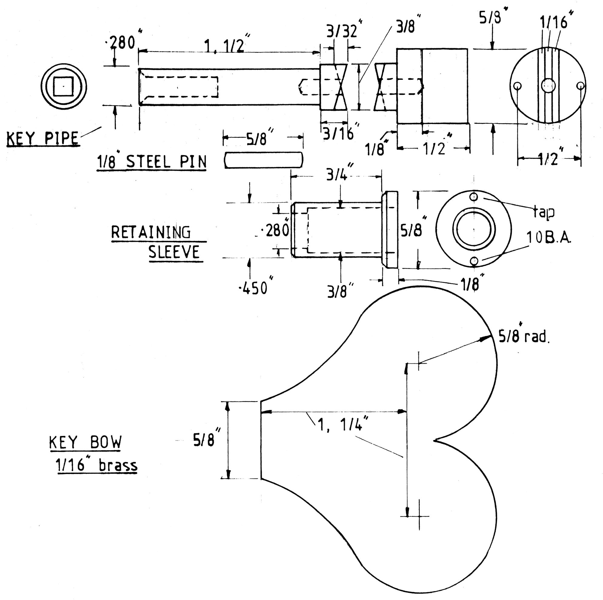
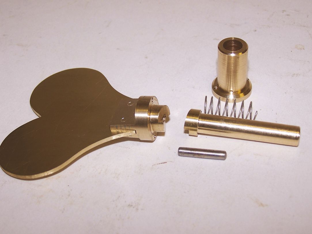
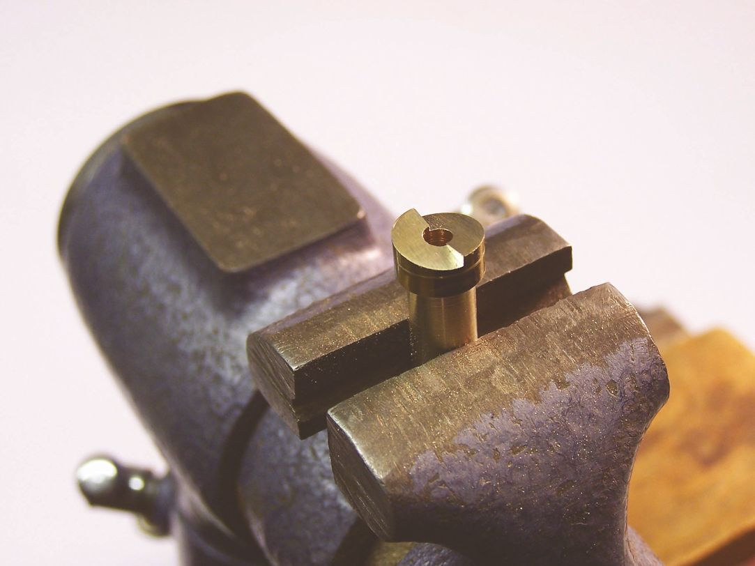
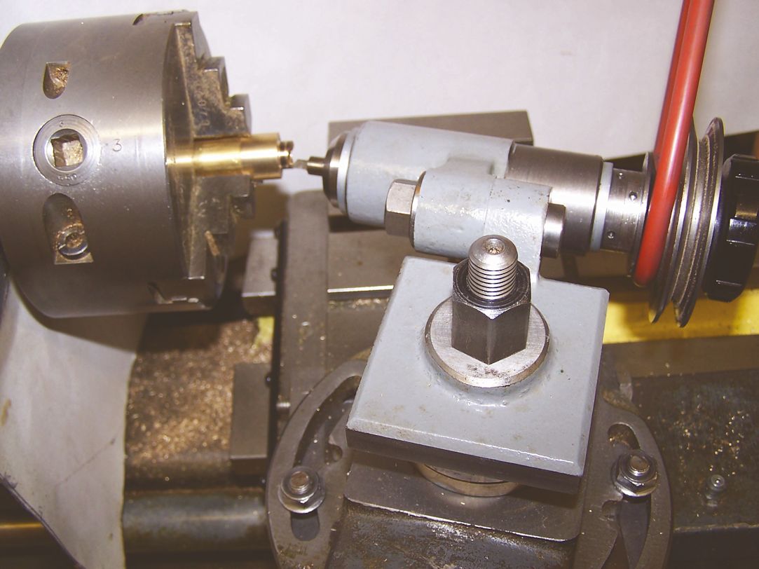
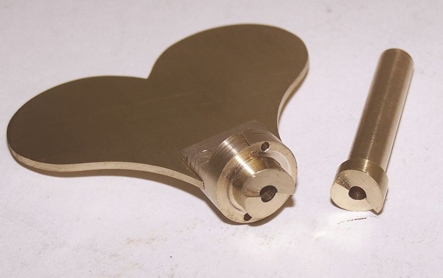
The key disassembled is shown in figure 2 where you can see that it consists of three parts plus a spring and a short locating pin. The pipe can be made first. This is from 3/8in brass bar. A length is held in the three-jaw chuck with some 2in extending from the chuck jaws. This is reduced to .280in as depicted on the drawing. The work is then parted off and reversed in the chuck to face the other end true and drill a 1/8Ē hole. The 3/8in diameter should be 3/16in in length. With a lathe tool a mark should be made to indicate the depth of the ratchet teeth. The forming of these can be done by filing. Figure 3 illustrates the filing of the slopes; a rectangular file with a safe edge will be required. After completing the first tooth the work is rotated in the vice for forming the second one. Alternativly these teeth can be formed as a light milling operation in the lathe, figure 4. Here a Potts milling spindle is secured in the lathe tool post, this is angled as shown here. A 1/4in homemade D-type end mill is held in the spindle and each tooth machined in turn rotating the lathe chuck through 180 degrees between each cut.
The rear end of the pipe to which the key bow is attached is provided with similar teeth but it is better to leave this until the slotting of the key fixing has been completed. A length of 5/8in diameter stock is held in the three-jaw chuck and a 1in length reduce to 3/8in. This will be shortened at a later stage for filing the other two teeth. At present this 1in length can be clamped in the tool post and fed into a 1/16in slitting saw mounted between centres in the lathe. However work like this can be done perfectly well with a hacksaw and following up with needle files to make the slot a close fit on the key bow; this is how I did it.
At this stage the square hole in the pipe can be made. Although this can be broached, I always form it by drilling and filing. The winding square is measured with a micrometer and a hole drilled in the pipe slightly larger. The filing is started by forming the four corner positions with a three-square file followed by a square file and finally with a rectangular file which will probably need reducing in width on the bench grinder. The fact that the hole was drilled slightly oversize will assist in giving a visible witness to the accuracy of the square.
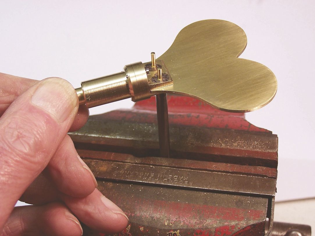
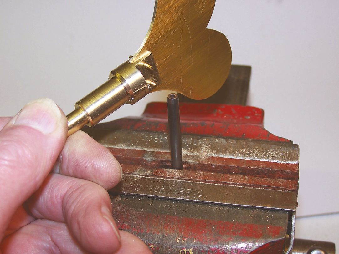
The retaining sleeve is straightforward turning in the lathe. The key bow can be secured with No 12 brass clock pins Figures 5 and 6 show how a hollow punch can be held in the vice for driving the pins in. they are then cut off and can be riveted on a steel stake and finally filed flush.
Figure 7 illustrates the two parts of the pipe each with the 1/8in hole drilled. It might be thought a good idea to fit the steel pin permanently in one half, but it is better if it is a sliding fit in both halves as it is very difficult to carry out any further remedial filing on the teeth once the pin is permanently fixed.
I havenít mentioned the spring. It is possible to buy an assortment of springs which is what I had. Failing that a spring can be wound up from spring wire on a mandrel in the lathe.
This key is of robust proportions because it is used to wind a fairly heavy weight in the month-going Regulator.
Download a pdf of this article
|
|

